|
Listen to this article
|

In the automation world, there can be a fine line between what is considered a motion controller and what represents a basic servo drive. It is critical to understand the functionality and intelligence of each device since, in many applications, both a motion controller and a servo drive are required to complete the system.
The servo system
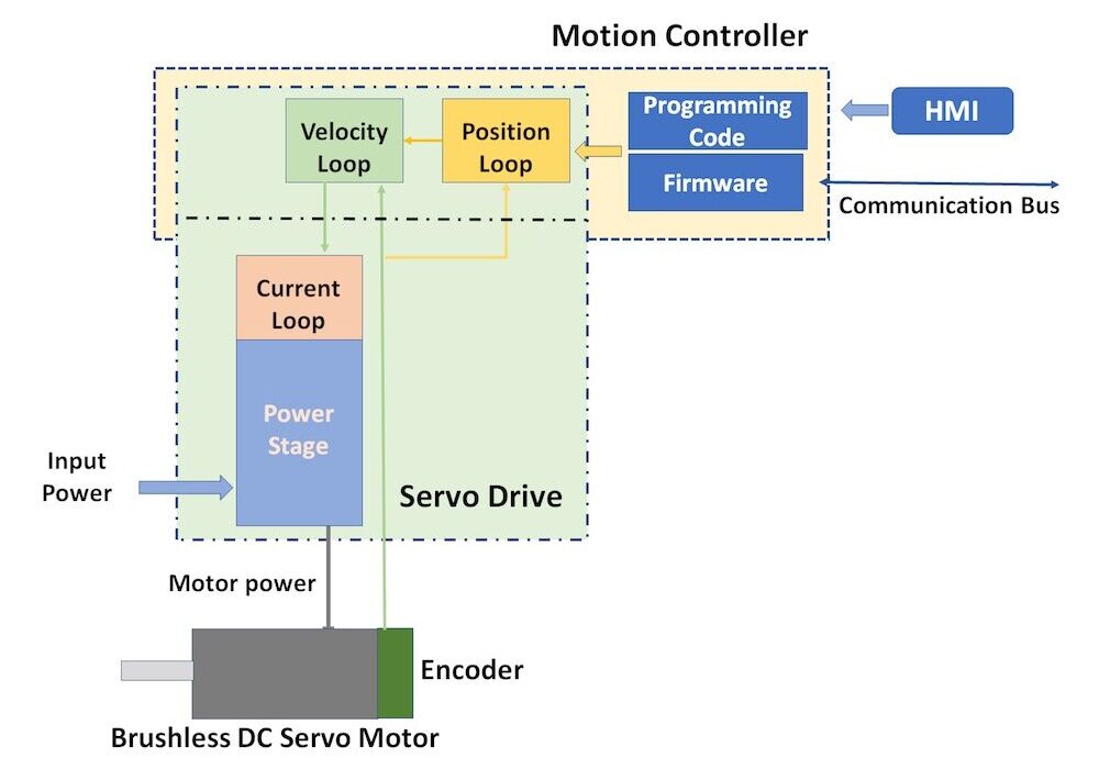
A servo motor is powered by a servo drive that supplies voltage and current to the motor coils and then monitors feedback to close the servo loop. In most cases, the servo drive consists of three embedded servo loops – the current (or torque) loop, velocity loop, and position loop – that interact with each other to create precision motion. The expected motor operation will determine which loops are required.
- In a torque control application, which requires a specific torque, only a current loop is needed. Since torque is directly proportional to current, torque is regulated by a sensor that provides current feedback to the servo drive.
- With velocity control applications, it is common to find both current and velocity loops. The velocity loop monitors a sensor that provides velocity information to the servo drive and then uses this data to adjust the current loop to increase or decrease torque.
- Finally, a position loop application employs a feedback sensor coupled to the motor that sends position information to the servo drive or motion controller, which in turn signals the velocity loop to increase or decrease velocity, which then relays the information to the current loop to regulate torque.
Defining the drive and controller roles
In a torque control application of a brushless dc servo motor, a “device” supplies current and voltage to a motor based on a commanded input measured against the current feedback. The apparatus that provides the power to the motor is called, in proper terms, a servo amplifier or servo drive. A current or torque drive is useless unless it receives a specific command to tell it what torque to produce. The command can come from a variety of sources that essentially act as the “controller”. The command may be as simple as a person, functioning as a controller, manually adjusting a potentiometer to apply a +/- 10 Vdc signal to the drive based on the desired output torque.
 In a typical brushless dc servo system, three embedded loops with various compensation and filtering elements are present. The inner loop (the current loop) is controlled by the velocity loop, which in turn is controlled by the position loop. The current loop always resides in the drive, while the velocity and position loops reside in either the drive or controller. The current loop uses a motor current sensor to measure current in the motor windings, while the velocity loop uses a speed sensor (typically an encoder) to measure motor velocity, which also provides position information to close the position loop.
Motion controllers are microprocessor-based devices with complex algorithms that generate Pulse Width Modulated (PWM) waveforms. Power transistors within the servo drive transfer the current and voltage waveforms to energize the motor. The motion controller typically processes the feedback information from the various servo loops. Controllers use feedback information to commutate the motor to behave precisely as commanded by the microprocessor. In essence, the intelligence provided by the microprocessor acts as the controller, while the electronics associated with the power devices acts as the drive. Basically, a controller is the element that applies a specific command to a position, velocity, or current loop, while a drive provides the voltage and current to the motors as demanded by the controller.
The controller is typically a programmable device that stores and runs code provided by the programmer. Programming is developed in a variety of languages, such as BASIC, C+/C++, VB, and languages specified in IEC 61131-3 standards. Controllers have numerous safety elements to prevent overloads or stop motion in the event of component failures. Drives, on the other hand, tend to focus on receiving the input commands of the controller and switching the power transistors on and off. This creates the current and voltage required to meet the commanded torque and speed.
With advances in microprocessors and new switching devices, controllers and drives are becoming more and more intertwined – mostly in centralized systems where all electronics are co-located in a single control cabinet. In decentralized solutions, the motion controller resides in the cabinet while the drives are collocated near the motors and communicate with the centralized motion controller through a motion field bus.
Editor’s Note: This article was written by a team of motion and automation experts at Kollmorgen, including engineers, customer service and design experts.


Tell Us What You Think!